Coast Artillery: Fire Control
 and Azimuth Scope (right)")
Depression Range Finder (left) and Azimuth Scope (right)
Fire Control Basics
Coast artillery fire control is an immensely complicated subject and any description will vary widely with the date and location. The term fire control evolved over the years, including position finding and fire direction. In its broader sense, however, the term has meant the science of arranging for the projectile (shot or shell) and the target (normally a ship) to meet at the same place and time. This brief outline applies principally to major-caliber gun batteries and less so to mortar and rapid-fire batteries.
-
Position Finding: The most obvious element of fire control is identifying the target and determining its location by either horizontal or vertical triangulation. The horizontal-base system used azimuth-reading telescopes in azimuth instruments to measure the horizontal angles to the target from two base end stations, which were a precisely measured distance apart. The vertical base system operated with just one station, using the telescope of a depression position finder (DPF) to waterline the target while measuring the angle the telescope was depressed below the horizontal to calculate the range. A DPF could also be used in place of an azimuth instrument in the horizontal base system. The precise time was critical in plotting a moving target, since the target location was only correct for a brief instant in time. The time-interval system used a timer that rang bells in both the plotting room and range-finding stations at pre-set intervals of 15 to 30 seconds. The reading by the observer was made when the time-interval bell rang. The observers could only ascertain the present location of the target. Their readings were immediately phoned to the plotting room, where they were plotted on a large plotting board grid. Several successive points were plotted, and based on these points the course of the target would be estimated, producing apredicted point – where the target was expected to be when the gun was fired after a pre-determined interval. However, the projectile would take some time to reach the predicted point, while the target continued to move. Since the target would no longer be at the predicted point when the shell arrived, the time of flight was calculated, based on the range, and a set-forward rule was used on the plotting board to determine the set-forward point, where the target was expected to be after a lapse of time equal to the time of flight. Using the time-interval system, the gun was fired at the calculated azimuth (the horizontal angle from due south), elevation (or range), and instant when the time of flight would bring the projectile to the moving target. This process was described as Case Three Pointing.
- Pointing: The gun could be pointed using one of three different cases. In Case One, normally used for rapid-fire guns, the gunner aimed his sight at the selected point on the target, with the sight adjusted to compensate for both azimuth and elevation. When the target could be seen from the gun, Case Two was normally used. Deflection, the horizontal adjustment to the sight, was calculated and placed on the sight, but the elevation angle was determined by the plotting room before being set on the gun, using the range disk or the quadrant. Case Two was the primary method used by major-caliber coast artillery. Case Three was used for mortar batteries and some later barbette batteries, when the target could not be seen from the gun, either due to the design of the battery, or due to range, weather conditions, or smoke screens. In this case, the azimuth and elevation were calculated in the plotting room and transmitted to the guns. The azimuth was set on the azimuth circle around the gun carriage, and the elevation was set on the range disk or quadrant.
- Corrections to the Gun Elevation: The gun elevation needed to give the predicted range to the target was listed in the firing tables. However, this was based on standard conditions, and actual conditions were never standard. The range tables, therefore, contained adjustments for non-standard conditions. A key factor was the muzzle velocity, which determined the range. The muzzle velocity in turn was affected by the characteristics of the individual powder lot, by the temperature of the powder, and by the erosion of the gun tube. Since the range was the most critical element of the fire control solution, these adjustments were carefully calculated. The muzzle velocity from the last firing of the same powder lot, when known, was taken as the standard. In addition, before target practice, several rounds were fired to establish the velocity. Other tables or analog devices adjusted for non-standard temperature, the component of the wind parallel to the trajectory, the density of the air, and for the height of the gun above sea level.
- Corrections to the Gun Azimuth: The rotation of the projectile caused it to veer to the right, called drift. Also, the component of the wind at right angles to the trajectory had to be adjusted for. Lastly, when the azimuth to the target was determined by the telescopic sight, an adjustment was necessary for the motion of the target. The combination of these adjustments, called the deflection, was used to offset the aiming point of the sight horizontally.
- Spotting: The final step in the fire control process was to observe the impact of the projectile and make corrections to bring the impact onto the target. Although the fire control system was intended to be highly accurate, it was not perfect, and factors such as weather and muzzle velocity required a certain amount of estimation. Spotting was intended to correct theory with practice. The process of correcting the fire was not simple, and coast artillery officers all too often failed to apply the complicated rules correctly. By World War II, spotting had become increasingly important, and base end stations normally had two instruments, either a depression position finder or an azimuth instrument for observation, and an azimuth instrument for spotting. A station designated B2S2, for example, would contain one telescope for observing the target (B2) and one azimuth instrument for spotting (S2).
- Communication: The basic means of communication was the telephone, which was sufficiently developed to be useful shortly after the turn of the century. Several analog devices were used and abandoned, including the telautograph and the aeroscope. In addition, mechanical data transmission systems were used at a number of batteries to transmit firing data. One of several mechanical systems, whether with rods, chains, or cables, ran from the plotting room to the guns, where the data was displayed. During World War II, match-the-pointer data-transmission systems were used for the same purpose, primarily with rapid-fire AMTB batteries, and with gun data computers. As a supplement to the telephone system, radio was used as a secondary method, especially for distant fire control stations.
- Reduced Visibility Problem: Before World War II the entire fire control system was based on visual tracking of targets, and reduced visibility posed a particular problem. At night, seacoast searchlights enabled the defenders to detect and target enemy warships. When fog, snow, or other inclement weather prevented observers from identifying and tracking their targets, all that could be done was to assume that the warships would be equally hampered. In addition, submarine mines were not as affected by reduced visibility, and so they formed a vital part of the combined defenses. By the latter part of World War II, radar eliminated the problem of reduced visibility.
- The Long-Range Problem: With the development of long-range barbette batteries after World War I, a difficult problem arose. It was now possible to fire guns over the horizon, beyond the view of the fire control stations. For two decades, the Coast Artillery Board wrestled with this problem, and as a partial solution, experimented with aerial observation, from both tethered balloons and aircraft, neither of which was entirely successful. In the end, perhaps the most successful technique was to place the fire control stations, and later radar, on elevated sites, which significantly increased their range to the horizon. Otherwise, all that could be done was to build tall towers for observers and radar.
- World War II: By the middle of World War II, two technological advances significantly changed coast artillery fire control. The most striking was the development of radar, which, as noted, could function in any weather or visibility. In addition, after decades of experimentation and development, largely stymied by inadequate funding, the coast artillery adopted gun data computers, primarily for the last generation of batteries. These replaced the plotting boards and, coupled with direct-reading observation instruments, substantially automated the fire control process, reducing the human error that had always plagued the system.
Position finding equipment was designed to collect accurate and rapid data to:
- Correctly identify the target.
- Determine the speed and direction of the target.
- Determine the true range of the target from the directing point of the battery at any instant.
- Predict the position of the target at any instant in advance of its present position.
- Make ballistic corrections due to atmospheric or other conditions existing at the moment of firing.
- Make corrections due to range difference between directing point and location of the gun.
- Make adjustments to place center of impact of fire from guns on target.
- Determine deflection to be set on gun so that when fired, it will allow for the travel of the target during the time of flight of the projectile, and effect of wind and drift on the flight of the projectile.
For a battery of 6-inch caliber or larger the operation of determining firing data for a moving target was divided into the following steps:
- Tracking-which included observing and plotting successive positions of the target.
- Determination of the set-forward point-which predicted the future position of the target, that is, its predicted position at the end of the projectile’s time of flight.
- Relocation-which determined the range and direction of the future position of the target from the directing point.
- Calculation of firing data-which consisted of converting the relocation data into firing data for use in pointing the guns.
The three standard systems of position finding used by seacoast artillery were:
- horizontal base
- vertical base
- self-contained base systems
.
In all of these systems the procedures were similar. They differed only in the method of locating the target in tracking. The first step in all position finding systems was the identification and location of the position of the assigned target with respect to the observation stations (base end stations) of the battery. This operation was called tracking and consisted of locating, at regular intervals of time by observation from one or more stations, successive positions of the target, and plotting those positions on a plotting board. The time interval between successive observations was called the observing interval and was 15 to 30 seconds in length (this varied from battery to battery). The observing intervals were indicated by TI (time interval) bells or buzzers which sounded simultaneously in all stations of the battery.
HORIZONTAL BASE SYSTEM
Description. In the horizontal base system, the target was located by the method of intersection used in surveying in which the direction of the target from two known points was determined. In the triangle involved, one side and the two adjacent angles were known. The solution was made graphically on the plotting board. The system required a base line on the ground, the azimuth and length of which had been accurately determined by surveying; two observation stations, one at each end of the base line, in each of which was mounted an instrument for measuring azimuths; a plotting room with plotting board; and the necessary communication lines. By 1944 most major caliber batteries had six to ten different possible baselines. The plotting board represented to scale the field of fire of the battery. On it was located to scale, in their proper relation to each other, the observation stations, the base line, and the directing point (the point for which the firing data are to be determined). The figure above illustrates the relation between the installations in the field and the set-up on the plotting board.
Operation. The observers at the base end stations sighted and followed the target with the vertical cross wires of their instruments on a designated point on the target assigned by the battery commander. At the sounding of the TI bell, the observers stopped following the target with their instruments while the readers read the azimuths and then resumed tracking. Each reader was equipped with a telephone head set connecting him to an operator, called an arm setter,in the plotting room. There the successive observations were plotted on the plotting board. The plotting board had an arm corresponding to each of two observation stations with a means of setting each arm in azimuth. Each arm setterset his arm to the azimuth read by the corresponding reader. The point of intersection of the arms represented the position of the target at the instant the observations were taken. This point was marked by the plotter. The operation was repeated at the sounding of each successive TI bell. The points were called plotted points. A line joining the plotted points represented the track or path of the target.
VERTICAL BASE SYSTEM
.
Description. In the vertical base system, the target was located by the offset method used in surveying, in which the direction and distance of the target from a known point were determined. The direction was determined by reading the azimuth as in the horizontal base system. The distance was determined by the depression angle method which involved the solution of a vertical right triangle of which the known leg was the effective height of the observation instrument above sea level, the hypotenuse was the line of sight from the observer to the target, and the unknown leg was the desired range to the target. The known angle was the complement of the angle between the hypotenuse and the known side, corrected for refraction. It was the angle through which the line of sight was depressed from the horizontal to intersect the target and was called the depression angle. The triangle was solved mechanically by the observation instrument called a depression position finder (DPF). This system required but one observation station, the azimuth and range to the target being read from the same instrument.
Wikipedia: the Depression Position Finder
Operation. The observer tracked the target in azimuth with the vertical cross wire as in the horizontal base system. At the same time he tracked the target in range with the horizontal cross wire. In the plotting room, only one arm of the plotting board was used. The azimuth and range was received from the reader at each sounding of the TI bell. The arm setter set the arm in azimuth and repeated the range to the plotter who marked the point at that range by means of range graduations along the edge of the arm.
SELF-CONTAINED BASE SYSTEM
Description. In the self-contained base system, the target was located by the offset method as in the vertical base system. The azimuth (direction) and range were determined by means of a self-contained range finder of either the coincidence (coincidence range finder or C.R.F.) or the stereoscopic type.
Operation. The operation of tracking with this system was similar to that with the vertical base system except that azimuths may have been read from a separate instrument.
Fire control stations dot the coastline near many major American harbors. People coming across these nondescript military structures frequently, if erroneously, call them pill boxes, bunkers, lookout posts, or machine gun nests. In actuality these stations are remnants of the once-extensive network of army seacoast defenses that protected the United States during the first half of the 20th Century. These stations served as the eyes for seacoast guns that surrounded the harbors, taking measurements to enable gunners to precisely locate enemy ships, and controlling the submarine mines that guarded the harbors.
Technically, battery fire control stations for use with vertical-base systems were not base end stations, but the term was generally used for all position-finding stations. These stations came in several styles, usually reflecting the eras when they were constructed and the location where they were built. The first fire control stations, crows nests, were small stations set into the battery parapets. The first separate stations at most harbor defenses began to appear just after the turn of the century. Army engineers frequently grouped five or six stations within a few dozen yards of each other, or several stations were located in large, multi-story frame buildings. Many clusters of fire control stations, especially primary stations, were within existing army forts. Secondary (and higher) stations were usually located some distance away. When possible, they too were located on government land, such as another fort, but often, especially during World War II, they were on small, military reservations purchased or leased for the purpose.
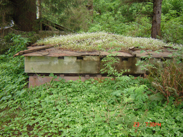
Where high land was close to the water, stations were often originally built on the reverse slope of hills; only their tops high enough to see or be seen. Later, simple rectangular structures were buried with only the top two or three feet exposed. A vision slit, usually with steel shutters, faced the sea. Interiors allowed just enough space for a cramped crew of soldiers to operate their telescopes and communications equipment. At other coastal locations, such as along much of the Gulf and South Atlantic Coasts, the land was relatively low and base end stations had to be elevated. Most of these stations consisted of a one, two, or three-floor house atop or otherwise integrated into a wood, metal, or concrete tower.
-
- Restored Plotting Room, Battery Osgood-Farley, Fort MacArthur Museum, San Pedro, CA (Joe Janesic)
-
- Restored Battery Commander’s Station, Battery Osgood-Farley, Fort MacArthur Museum (Joe Janesic)
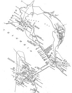
Fire Control Network at the Harbor Defenses of the Columbia River in 1934 (For symbol key download this PDF: Symbols 1940)